
HIOKI Clamp On Power Logger
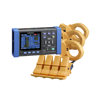
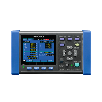


HIOKI Clamp On Power Logger
Model: PW3365
Brand: Hioki
Origin: Japan
概括
Eliminate the Risk of Short-Circuits and Electrical Accidents
Hioki Clamp On Power Meters are multi-channel power measuring devices utilizing clamp sensor input to accurately and safely measure power on single-phase to three-phase lines. The PW3365 power logger takes safety and convenience one step further by being the world’s first non-metallic contact power meter that utilizes completely covered voltage clips that can be attached to any part of a cable or busbar. Customers can now monitor power demand and other power parameters to aid in energy audits and validate energy saving measures without risk of short-circuit accidents, power interruptions, or bodily injury due to electrocutions.
Award
- German Design Award Special 2016 (For Voltage Sensor PW9020)
- 2015 The Nikkan Kogyo Shimbun MACHINE DESIGN AWARD Distinctive Merit Award (For PW3365)
Safely and easily measure power without the need to shut off the circuit breaker first with a clamp-on power logger
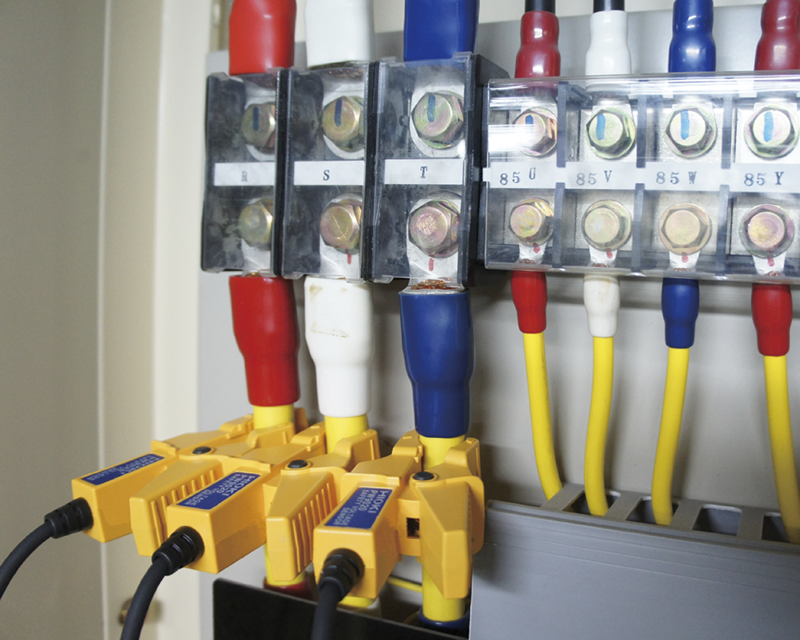
Although technicians had to connect instruments to metal terminals in order to measure voltage when measuring power in the past, Hioki’s newly developed no-metal-contact voltage sensor makes it possible to measure voltage simply by clamping the sensor around an insulated wire. This approach completely eliminates the risk of short-circuits since metal never comes into contact with live components, and it simplifies the sensor attachment process even when terminals are covered since the sensor can be simply clipped around the cable without removing the cover.
Harmonic Testing | Analyze from the fundamental wave up to the 13th order with the PW3365 Clamp On Power Logger (from version 2.00)
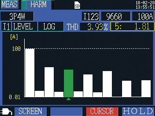
Use the Hioki PW3365 Clamp On Power Logger to analyze the fundamental waveform up to the 13th order of harmonic components that are included in the voltage and current signals of 50/60Hz power lines. Display the total harmonic distortion (THD) and RMS and harmonic content of each harmonic order as a numerical list or graph. In particular, you can now safely and easily measure the 5th and 7th harmonic within the harmonic component which tend to have the greatest impact on power quality.
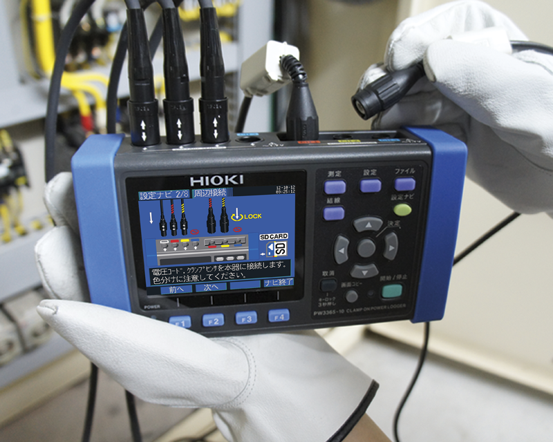
Graphical, easy-to-understand guidance on how to connect the clamp-on power logger
The PW3365’s Quick Setup feature guides you through the process of setting up the instrument for measurement, right up to starting measurement, to make even 3-phase power measurement a breeze. Since any mistaken connections will trigger a FAIL message, the feature also helps prevent measurement mistakes.
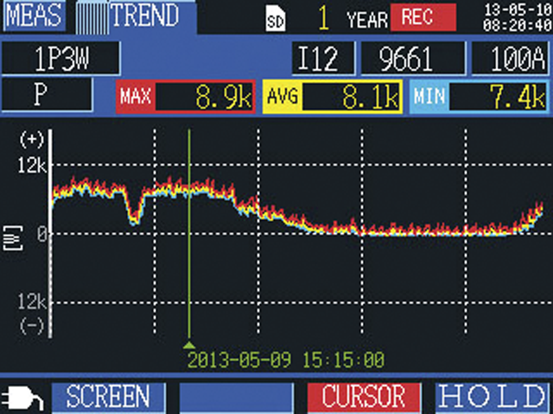
Display clamp-on power logger measurement results as a graph so you can review them at a glance
The PW3365 displays recorded measured values as a graph for convenient use in power management. In addition to instantaneous measured values, you can review maximum, minimum, and average values by moving the cursor on the demand and trend graph displays.
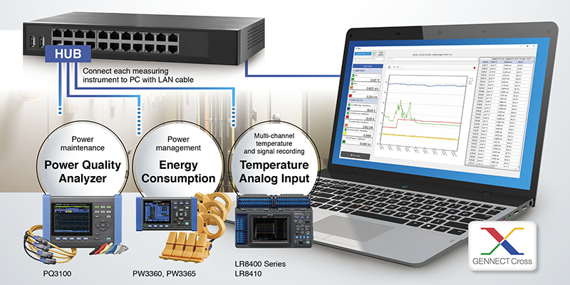
Get results from the job site in real-time, GENNECT CROSS SF4000
Capture data on the PC while testing remotely
Accuracy guaranteed: 1 year
| Measurement line & number of circuits | 50/60 Hz, Single phase 2 wires (1/2/3 circuits), Single phase 3 wires (1 circuit), Three phases 3 wires (1 circuit), Three phases 4 wires (1 circuit), Current only: 1 to 3 channels | |||||
|---|---|---|---|---|---|---|
| Measurement items | Voltage RMS, current RMS, voltage fundamental wave value, current fundamental wave value, voltage fundamental wave phase angle, current fundamental wave phase angle, frequency (U1), voltage waveform peak (absolute value), current waveform peak (absolute value), active power, reactive power, apparent power, power factor (with lag/lead display) or displacement power factor (with lag/lead display), active energy (consumption, regeneration), reactive energy (lag, lead), energy cost display, active power demand quantity (consumption, regeneration), reactive power demand quantity (lag, lead), active power demand value (consumption, regeneration), reactive power demand value (lag, lead), power factor demand | |||||
| Voltage ranges | 400 V AC (Effective measurement range: 90.0 V to 520.0 V) | |||||
| Harmonic | Harmonic voltage, harmonic current, voltage total harmonic distortion (THD-F or THD-R), current total harmonic distortion (THD-F or TDH-R), up to 13th order | |||||
| Current ranges | 500.00 mA to 5.0000 kA AC (depends on current sensor in use), 50.000 mA to 5.0000 A AC (Leak clamp on sensor only) |
|||||
| Power ranges | 200.00 W to 6.0000 MW (depends on voltage/current combination and measured line type) | |||||
| Basic accuracy | Voltage : ±1.5% rdg. ±0.2% f.s(combined accuracy with PW3365-20 + PW9020) Current : ±0.3% rdg. ±0.1% f.s. + clamp sensor accuracy Active power : ±2.0% rdg. ±0.3% f.s. + clamp sensor accuracy (at power factor = 1) |
|||||
| Display update rate | 0.5 sec (except when accessing SD card or internal memory, or during LAN/USB communication) | |||||
| Save destination | SD/SDHC Memory card, or internal memory at real time | |||||
| Data save interval | 1 sec to 30 sec, 1 minute to 60 minutes, 14 selections | |||||
| Save items | Measurement value save: Average only / Average, Maximum, Minimum value Screen copy: BMP form (saved every 5 min. at minimum interval time) Waveform save: Binary waveform data |
|||||
| Interfaces | SD/SDHC memory card, LAN 100BASE-TX: HTTP server function, remote settings via communication program, data download, USB 2.0: When connected to a PC, the SD Card and internal memory are recognized as removable storage devices, remote settings via communication program, data download | |||||
| Functions | Connection check, Quick Set navigation guide, clock | |||||
| Power supply | AC adapter Z1008: (100 to 240 V AC, 50/60 Hz), 45 VA (including AC adapter) Battery pack 9459: (DC 7.2 V, 3 VA, charging time 6 hr 10 m), 5 hours of continuous use (with back light off) |
|||||
| Dimensions and mass | 180 mm (7.09 in)W × 100 mm (3.94 in)H × 48 mm (1.89 in)D, 540 g (19 oz) without PW9002 180 mm (7.09 in)W × 100 mm (3.94 in)H × 68 mm (2.68 in)D, 820 g (28.9 oz) with PW9002 |
|||||
| Included accessories | Safety Voltage Sensor PW9020 ×1 set, AC adapter Z1008 ×1, USB cable ×1, Instruction manual ×1, Measurement guide ×1, Color clip (red, yellow, blue and white each 4), Spiral tubes in black (cord bundling for current sensors and voltage sensors) ×10 | |||||
应用

Award
- German Design Award Special 2016 (For Voltage Sensor PW9020)
- 2015 The Nikkan Kogyo Shimbun MACHINE DESIGN AWARD Distinctive Merit Award (For PW3365)

Safely and easily measure power without the need to shut off the circuit breaker first with a clamp-on power logger
Although technicians had to connect instruments to metal terminals in order to measure voltage when measuring power in the past, Hioki’s newly developed no-metal-contact voltage sensor makes it possible to measure voltage simply by clamping the sensor around an insulated wire. This approach completely eliminates the risk of short-circuits since metal never comes into contact with live components, and it simplifies the sensor attachment process even when terminals are covered since the sensor can be simply clipped around the cable without removing the cover.

Harmonic Testing | Analyze from the fundamental wave up to the 13th order with the PW3365 Clamp On Power Logger (from version 2.00)
Use the Hioki PW3365 Clamp On Power Logger to analyze the fundamental waveform up to the 13th order of harmonic components that are included in the voltage and current signals of 50/60Hz power lines. Display the total harmonic distortion (THD) and RMS and harmonic content of each harmonic order as a numerical list or graph. In particular, you can now safely and easily measure the 5th and 7th harmonic within the harmonic component which tend to have the greatest impact on power quality.

Graphical, easy-to-understand guidance on how to connect the clamp-on power logger
The PW3365’s Quick Setup feature guides you through the process of setting up the instrument for measurement, right up to starting measurement, to make even 3-phase power measurement a breeze. Since any mistaken connections will trigger a FAIL message, the feature also helps prevent measurement mistakes.

Display clamp-on power logger measurement results as a graph so you can review them at a glance
The PW3365 displays recorded measured values as a graph for convenient use in power management. In addition to instantaneous measured values, you can review maximum, minimum, and average values by moving the cursor on the demand and trend graph displays.

Get results from the job site in real-time, GENNECT CROSS SF4000
Capture data on the PC while testing remotely
规格
Accuracy guaranteed: 1 year
| Measurement line & number of circuits | 50/60 Hz, Single phase 2 wires (1/2/3 circuits), Single phase 3 wires (1 circuit), Three phases 3 wires (1 circuit), Three phases 4 wires (1 circuit), Current only: 1 to 3 channels | |||||
|---|---|---|---|---|---|---|
| Measurement items | Voltage RMS, current RMS, voltage fundamental wave value, current fundamental wave value, voltage fundamental wave phase angle, current fundamental wave phase angle, frequency (U1), voltage waveform peak (absolute value), current waveform peak (absolute value), active power, reactive power, apparent power, power factor (with lag/lead display) or displacement power factor (with lag/lead display), active energy (consumption, regeneration), reactive energy (lag, lead), energy cost display, active power demand quantity (consumption, regeneration), reactive power demand quantity (lag, lead), active power demand value (consumption, regeneration), reactive power demand value (lag, lead), power factor demand | |||||
| Voltage ranges | 400 V AC (Effective measurement range: 90.0 V to 520.0 V) | |||||
| Harmonic | Harmonic voltage, harmonic current, voltage total harmonic distortion (THD-F or THD-R), current total harmonic distortion (THD-F or TDH-R), up to 13th order | |||||
| Current ranges | 500.00 mA to 5.0000 kA AC (depends on current sensor in use), 50.000 mA to 5.0000 A AC (Leak clamp on sensor only) |
|||||
| Power ranges | 200.00 W to 6.0000 MW (depends on voltage/current combination and measured line type) | |||||
| Basic accuracy | Voltage : ±1.5% rdg. ±0.2% f.s(combined accuracy with PW3365-20 + PW9020) Current : ±0.3% rdg. ±0.1% f.s. + clamp sensor accuracy Active power : ±2.0% rdg. ±0.3% f.s. + clamp sensor accuracy (at power factor = 1) |
|||||
| Display update rate | 0.5 sec (except when accessing SD card or internal memory, or during LAN/USB communication) | |||||
| Save destination | SD/SDHC Memory card, or internal memory at real time | |||||
| Data save interval | 1 sec to 30 sec, 1 minute to 60 minutes, 14 selections | |||||
| Save items | Measurement value save: Average only / Average, Maximum, Minimum value Screen copy: BMP form (saved every 5 min. at minimum interval time) Waveform save: Binary waveform data |
|||||
| Interfaces | SD/SDHC memory card, LAN 100BASE-TX: HTTP server function, remote settings via communication program, data download, USB 2.0: When connected to a PC, the SD Card and internal memory are recognized as removable storage devices, remote settings via communication program, data download | |||||
| Functions | Connection check, Quick Set navigation guide, clock | |||||
| Power supply | AC adapter Z1008: (100 to 240 V AC, 50/60 Hz), 45 VA (including AC adapter) Battery pack 9459: (DC 7.2 V, 3 VA, charging time 6 hr 10 m), 5 hours of continuous use (with back light off) |
|||||
| Dimensions and mass | 180 mm (7.09 in)W × 100 mm (3.94 in)H × 48 mm (1.89 in)D, 540 g (19 oz) without PW9002 180 mm (7.09 in)W × 100 mm (3.94 in)H × 68 mm (2.68 in)D, 820 g (28.9 oz) with PW9002 |
|||||
| Included accessories | Safety Voltage Sensor PW9020 ×1 set, AC adapter Z1008 ×1, USB cable ×1, Instruction manual ×1, Measurement guide ×1, Color clip (red, yellow, blue and white each 4), Spiral tubes in black (cord bundling for current sensors and voltage sensors) ×10 | |||||


