DRUCK Modular Pressure Controller
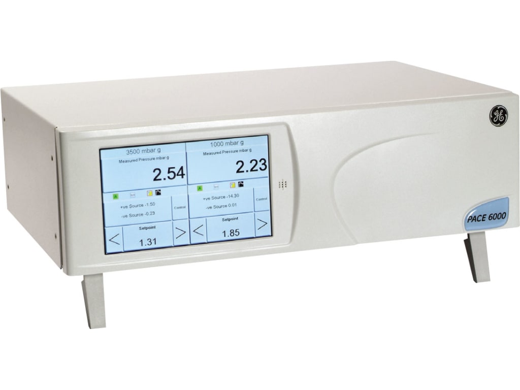

DRUCK Modular Pressure Controller
Model: PACE6000
Brand: druck
Origin: UK
概要
- Negative gauge calibration included as standard
- RS232 & IEEE connectivity as standard
- Analog O/P option
- High-resolution touch screen operation
- Easy to use intuitive icon-driven menu structure
-
Dual Channel Pneumatic, Modular Pressure Controller and Calibrator
The new PACE pneumatic modular pressure controller brings together the latest control and measurement technology from GE to offer an elegant, fast, flexible and economical solution to pressure control for automated production, test and calibration.
PACE employs full digital control to provide high control stability and high slew rate, while its digitally characterized pressure sensor offers the quality, stability, higher bandwidth and precision associated with this latest generation of piezo-resistive and resonant devices.
A new generation of high precision Druck pressure controller, designed for test bench, bench top and rack mount calibration, and automated test applications.
Test Program
The Test Program option provides a facility for creating, storing and executing numerous test procedures within the instrument itself. This is particularly useful for longer, more repetitive and laborious procedures requiring manual inputs for rapid prototyping, manufacturing and life cycle testing. Test Programs can also be transferred to a PC using a mass storage device for further editing, and copied back from the mass storage device to the instrument.
Leak Test
Leak Test applies a test pressure(s) to an external system connected to the instrument to determine the magnitude of pressure variations due to leaks. This application sets the test pressure and a dwell time to eliminate potential adiabatic effects at the test pressure and the leak test time period. On completion, the display shows the Start Pressure, End Pressure, Pressure Change and Leak Rate.
Switch Test
Switch Test automates the testing of pressure switch devices. Following the test, the display shows the pressure at which the contacts open and closes, and the switch hysteresis. Switch Test Task can also be set to loop (n) times to exercise a switch or capture switch toggle max, min and average values.
Analog Output
This option can be programmed via the setup menu screen to output a signal proportional to the instrument range selected. This allows the instrument to interface with PC or PLC I/O cards, remote displays, chart recorders or other data logging equipment.
Users can select outputs of 0 to 10 V, 0 to 5 V, -5 to 5 V and 0/4 to 20 mA. Precision with respect to host instrument measured pressure 0.05% FS over the host instrument operating temperature range, variable update rate to 80 readings per second. The option is programmable between minimum and FS pressure for proportional output against pressure.
Burst Test
Burst Test is a brand new application for the PACE Series designed primarily for manufacturers of pressure rupture discs, other safety critical devices, even medical products where it is important to accurately measure the exact point at which the elastic limit or point at which the device will rupture or burst will occur.
Accurate and precise measurement of this phenomenon enables scalable process improvement in the manufacture of these devices, improved safety in safety critical applications and improved quality of life in medical applications.
Volt Free Contacts
Volt Free Contacts enable control of peripheral devices such as vacuum pumps, ovens, etc. Each VFC option has three independent volt-free NO/NC relay contacts. A number of conditions can be set within a PACE instrument to trigger a relay toggling its contacts.
Aeronautical Option
Full control available in pure aeronautical units:
- Altitude - feet or meters
- Rate of Climb - feet or meters/minute, second
- Air Speed - knots or km/hour, mph
- Mach - mach number
Manufacturer Specs
| GE Druck Pace 6000 General Specifications | ||
| Pressure Measurement | ||
| Standard Pressure Ranges | 350 and 700 mbar gauge, 1, 2, 3.5, 7, 10, 20, 35, 70, 100, 135, 172 and 210 bar gauge 5, 10, 15, 30, 50, 100, 150, 300, 500, 1000, 1500, 2000, 2500, 3000 psi 35, 70, 100, 200, 350, 700 kPa, 1, 2, 3.5, 7, 10, 13.5, 17.2, 21 MPa All gauge versions available with negative calibration as standard. For absolute pressure ranges select any gauge range of 1 bar and above and add barometric option |
|
| Over Range Indication | 10% above mbar/bar full scale pressure range | |
| Pressure Media | Dry, oil free, non-corrosive gas maintained at a value of 10% above the maximum required output pressure. Dry air or Nitrogen recommended. | |
| For low pressure ranges below 350 mbar please consult your sales representative. | ||
| Display | ||
| Panel | 7” (17.5 cm) TFT colour VGA resolution wide format display with integral touchscreen. | |
| Comms Update Rate | 8 times per second | |
| Display Update Rate | 2 times per second | |
| Readout | ± 9999999 | |
| Pressure Units | mbar, bar, Pa(N/m 2 ), hPa, kPa, MPa, mmHg @ 0°C, cmHg @ 0°C, mHg @ 0°C,, inHg @ 0°C, mmH 2 O @ 4°C, cmH 2 O @ 4°C, mH 2 O @ 4°C, mmH 2 O @ 20°C, cmH 2 O @20 °C, mH 2 O @ 20 °C, kg/m 2 , kg/cm 2 , torr, atm, psi, lb/ft 2 , inH 2 O @ 4°C, inH 2 O@ 20°C, inH 2 O @ 60°C, ftH 2 O @ 4°C, ftH 2 O @ 20°C, ftH 2 O @ 60°C, User Defined 1, User Defined 2, User Defined 3, User Defin | |
| Performance | ||
| Gauge Mode Precision | 0.005% Rdg + 0.005% FS includes linearity, hysteresis, repeatability and temperature effects for gauge pressures and assumes steady state temperature and regular zeroing. | |
| Negative Gauge Precision | Maximum error at any given pressure value is equal to maximum error at the equivalent positive pressure value. | |
| Absolute Mode Precision | Gauge mode precision + barometric reference precision | |
| Barometric Reference Precision | Optional barometric reference 0.05 mbar or 0.000725 psi. Includes non-linearity, hysteresis, repeatability and temperature effects between 15°C (59°F) and 45°C (113°F) | |
| Controller Stability | 0.001% FS | |
| Long term stability | To 0.01% reading per annum. 2 bar to 210 bar. 0.02% Rdg, 1bar & 0.03% Rdg, 350 mbar - 700 mbar. Barometer 0.1 mbar/ annum | |
| Gas Consumption | All supply gas is delivered to the system. No gas is used in measure mode, or when the instrument is turned off | |
| Aeronautical | ||
| Altitude range -3000 to +55,000 ft (Altitude precision based on 35 to 1150 mbar range ) | ||
| Sea level | ±2 ft | |
| 8500 ft | ±3 ft | |
| 35,000 ft | ±9 ft | |
| Airspeed range to 650 knots (Airspeed precision based on 1000 mbar g range) | ||
| 50 knots | ±1.00 kts | |
| 250 knots | ±0.21 kts | |
| 500 knots | ±0.11 kts | |
| (Specifications assume steady state and regular zeroing.) | ||
| Electrical | ||
| Power Supply | 90 V AC to 130 V AC @ 47 to 63 Hz & 180 V AC to 260 V AC @ 47 to 63 Hz. [Universal input.] | |
| Communications | ||
| Communication | RS232, IEEE-488, SCPI, DPI515, DPI510 and DPI500 emulation. Future expandability. | |
| Environmental | ||
| Temperature | Operating | 10°C to 50°C (50°F to 122°F) |
| Calibrated | 15°C to 45°C (59°F to 113°F) | |
| Storage | -20°C to 70°C (-4°F to 158°F) | |
| Sealing | IP20 | |
| Humidity | 5% RH to 95% RH non-condensing. | |
| Vibration | Compliant with Def. Stan. 66-31 8.4 Cat 3 and MIL-T-28800E Cat 2. | |
| Shock | Mechanical shock conforms to EN61010. | |
| Conformity | LVD EN61010, EMC EN61326, PED, ROHS & WEEE - CE marked. | |
| Physical | ||
| Weight | 12.5 kg or 27.5 lbs with single control module 17.5 kg or 38.5 lbs with dual control module | |
| Dimensions | 440 mm x 3U x 320 mm (17.3 in x 3U x 12.6 in) | |
| Accessories | ||
| Pneumatic Connections | G ⅛ female | |
| Optional: G ⅛ male to ⅛ NPT female adaptor*, G ⅛ male to 7/16 – 20 UNF female adaptor, G ⅛ male to ¼ NPT female adaptor*, G ⅛ male to AN4 37 Deg male adaptor, G ⅛ male to G ¼ female adaptor, G ⅛ male to AN6 37 Deg male adaptor, G⅛ male to ¼ I.D. hose adaptor. IO-ADAPTOR-KIT-contains one of each of the above adaptors. | ||
| *Required by US customers (5 for each control module) Differential connection kit Low Pressure Snubber reference port Diffuser gas exhaust Rack mount kit PACE6000 Negative gauge generator Vacuum system assembly |
||
| Options | ||
| Leak Test | ||
| Test Program | ||
| Switch Test [with electrical connector] | ||
| Analog O/P | ||
| Volt Free contacts | ||
| Burst Test | ||
| Aeronautical | ||
| Calibration | ||
| UKAS calibration PACE6000 (per module) | ||
Tech Specs
Test Equipment General Attributes |
|
|---|---|
| Shipping Weight | 20.00 LBS |
| HTS/Schedule B Number | 9032890090 |
| ECCN Number | EAR99 |
| Country of Origin | UK/China |
応用
Test Program
The Test Program option provides a facility for creating, storing and executing numerous test procedures within the instrument itself. This is particularly useful for longer, more repetitive and laborious procedures requiring manual inputs for rapid prototyping, manufacturing and life cycle testing. Test Programs can also be transferred to a PC using a mass storage device for further editing, and copied back from the mass storage device to the instrument.
Leak Test
Leak Test applies a test pressure(s) to an external system connected to the instrument to determine the magnitude of pressure variations due to leaks. This application sets the test pressure and a dwell time to eliminate potential adiabatic effects at the test pressure and the leak test time period. On completion, the display shows the Start Pressure, End Pressure, Pressure Change and Leak Rate.
Switch Test
Switch Test automates the testing of pressure switch devices. Following the test, the display shows the pressure at which the contacts open and closes, and the switch hysteresis. Switch Test Task can also be set to loop (n) times to exercise a switch or capture switch toggle max, min and average values.
Analog Output
This option can be programmed via the setup menu screen to output a signal proportional to the instrument range selected. This allows the instrument to interface with PC or PLC I/O cards, remote displays, chart recorders or other data logging equipment.
Users can select outputs of 0 to 10 V, 0 to 5 V, -5 to 5 V and 0/4 to 20 mA. Precision with respect to host instrument measured pressure 0.05% FS over the host instrument operating temperature range, variable update rate to 80 readings per second. The option is programmable between minimum and FS pressure for proportional output against pressure.
Burst Test
Burst Test is a brand new application for the PACE Series designed primarily for manufacturers of pressure rupture discs, other safety critical devices, even medical products where it is important to accurately measure the exact point at which the elastic limit or point at which the device will rupture or burst will occur.
Accurate and precise measurement of this phenomenon enables scalable process improvement in the manufacture of these devices, improved safety in safety critical applications and improved quality of life in medical applications.
Volt Free Contacts
Volt Free Contacts enable control of peripheral devices such as vacuum pumps, ovens, etc. Each VFC option has three independent volt-free NO/NC relay contacts. A number of conditions can be set within a PACE instrument to trigger a relay toggling its contacts.
Aeronautical Option
Full control available in pure aeronautical units:
- Altitude - feet or meters
- Rate of Climb - feet or meters/minute, second
- Air Speed - knots or km/hour, mph
- Mach - mach number
仕様
Manufacturer Specs
| GE Druck Pace 6000 General Specifications | ||
| Pressure Measurement | ||
| Standard Pressure Ranges | 350 and 700 mbar gauge, 1, 2, 3.5, 7, 10, 20, 35, 70, 100, 135, 172 and 210 bar gauge 5, 10, 15, 30, 50, 100, 150, 300, 500, 1000, 1500, 2000, 2500, 3000 psi 35, 70, 100, 200, 350, 700 kPa, 1, 2, 3.5, 7, 10, 13.5, 17.2, 21 MPa All gauge versions available with negative calibration as standard. For absolute pressure ranges select any gauge range of 1 bar and above and add barometric option |
|
| Over Range Indication | 10% above mbar/bar full scale pressure range | |
| Pressure Media | Dry, oil free, non-corrosive gas maintained at a value of 10% above the maximum required output pressure. Dry air or Nitrogen recommended. | |
| For low pressure ranges below 350 mbar please consult your sales representative. | ||
| Display | ||
| Panel | 7” (17.5 cm) TFT colour VGA resolution wide format display with integral touchscreen. | |
| Comms Update Rate | 8 times per second | |
| Display Update Rate | 2 times per second | |
| Readout | ± 9999999 | |
| Pressure Units | mbar, bar, Pa(N/m 2 ), hPa, kPa, MPa, mmHg @ 0°C, cmHg @ 0°C, mHg @ 0°C,, inHg @ 0°C, mmH 2 O @ 4°C, cmH 2 O @ 4°C, mH 2 O @ 4°C, mmH 2 O @ 20°C, cmH 2 O @20 °C, mH 2 O @ 20 °C, kg/m 2 , kg/cm 2 , torr, atm, psi, lb/ft 2 , inH 2 O @ 4°C, inH 2 O@ 20°C, inH 2 O @ 60°C, ftH 2 O @ 4°C, ftH 2 O @ 20°C, ftH 2 O @ 60°C, User Defined 1, User Defined 2, User Defined 3, User Defin | |
| Performance | ||
| Gauge Mode Precision | 0.005% Rdg + 0.005% FS includes linearity, hysteresis, repeatability and temperature effects for gauge pressures and assumes steady state temperature and regular zeroing. | |
| Negative Gauge Precision | Maximum error at any given pressure value is equal to maximum error at the equivalent positive pressure value. | |
| Absolute Mode Precision | Gauge mode precision + barometric reference precision | |
| Barometric Reference Precision | Optional barometric reference 0.05 mbar or 0.000725 psi. Includes non-linearity, hysteresis, repeatability and temperature effects between 15°C (59°F) and 45°C (113°F) | |
| Controller Stability | 0.001% FS | |
| Long term stability | To 0.01% reading per annum. 2 bar to 210 bar. 0.02% Rdg, 1bar & 0.03% Rdg, 350 mbar - 700 mbar. Barometer 0.1 mbar/ annum | |
| Gas Consumption | All supply gas is delivered to the system. No gas is used in measure mode, or when the instrument is turned off | |
| Aeronautical | ||
| Altitude range -3000 to +55,000 ft (Altitude precision based on 35 to 1150 mbar range ) | ||
| Sea level | ±2 ft | |
| 8500 ft | ±3 ft | |
| 35,000 ft | ±9 ft | |
| Airspeed range to 650 knots (Airspeed precision based on 1000 mbar g range) | ||
| 50 knots | ±1.00 kts | |
| 250 knots | ±0.21 kts | |
| 500 knots | ±0.11 kts | |
| (Specifications assume steady state and regular zeroing.) | ||
| Electrical | ||
| Power Supply | 90 V AC to 130 V AC @ 47 to 63 Hz & 180 V AC to 260 V AC @ 47 to 63 Hz. [Universal input.] | |
| Communications | ||
| Communication | RS232, IEEE-488, SCPI, DPI515, DPI510 and DPI500 emulation. Future expandability. | |
| Environmental | ||
| Temperature | Operating | 10°C to 50°C (50°F to 122°F) |
| Calibrated | 15°C to 45°C (59°F to 113°F) | |
| Storage | -20°C to 70°C (-4°F to 158°F) | |
| Sealing | IP20 | |
| Humidity | 5% RH to 95% RH non-condensing. | |
| Vibration | Compliant with Def. Stan. 66-31 8.4 Cat 3 and MIL-T-28800E Cat 2. | |
| Shock | Mechanical shock conforms to EN61010. | |
| Conformity | LVD EN61010, EMC EN61326, PED, ROHS & WEEE - CE marked. | |
| Physical | ||
| Weight | 12.5 kg or 27.5 lbs with single control module 17.5 kg or 38.5 lbs with dual control module | |
| Dimensions | 440 mm x 3U x 320 mm (17.3 in x 3U x 12.6 in) | |
| Accessories | ||
| Pneumatic Connections | G ⅛ female | |
| Optional: G ⅛ male to ⅛ NPT female adaptor*, G ⅛ male to 7/16 – 20 UNF female adaptor, G ⅛ male to ¼ NPT female adaptor*, G ⅛ male to AN4 37 Deg male adaptor, G ⅛ male to G ¼ female adaptor, G ⅛ male to AN6 37 Deg male adaptor, G⅛ male to ¼ I.D. hose adaptor. IO-ADAPTOR-KIT-contains one of each of the above adaptors. | ||
| *Required by US customers (5 for each control module) Differential connection kit Low Pressure Snubber reference port Diffuser gas exhaust Rack mount kit PACE6000 Negative gauge generator Vacuum system assembly |
||
| Options | ||
| Leak Test | ||
| Test Program | ||
| Switch Test [with electrical connector] | ||
| Analog O/P | ||
| Volt Free contacts | ||
| Burst Test | ||
| Aeronautical | ||
| Calibration | ||
| UKAS calibration PACE6000 (per module) | ||
Tech Specs
Test Equipment General Attributes |
|
|---|---|
| Shipping Weight | 20.00 LBS |
| HTS/Schedule B Number | 9032890090 |
| ECCN Number | EAR99 |
| Country of Origin | UK/China |


