HIOKI CHEMICAL IMPEDANCE ANALYZER
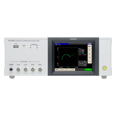
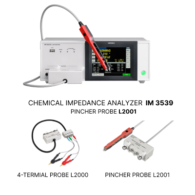
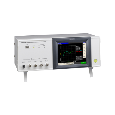


HIOKI CHEMICAL IMPEDANCE ANALYZER
Model: IM3590
Brand: Hioki
Origin: Japan
Summary
For R&D applications of Electrochemical Components and Materials, Batteries, and EDLCs
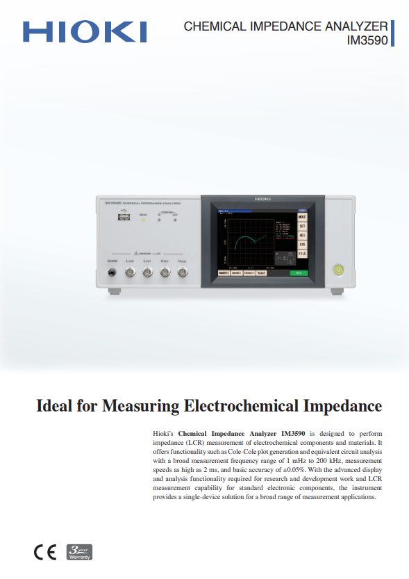
Hioki LCR Meters and Impedance Analyzers range from 1 mHz to 3 GHz devices to suit a wide range of applications in the testing of electronic components. The IM3590 impedance analyzer is an advanced component tester especially suited to electrochemical impedance measurements and includes a variety of graphing functions that are needed for battery and chemical material testing.
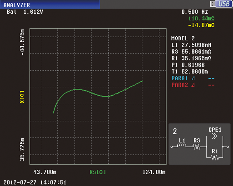
Cole-Cole plot generation, equivalent circuit analysis, and other impedance measurement capabilities
In addition to measuring electrochemical components and materials, batteries, and electrical double-layer capacitors, the Hioki IM3590 can generate Cole-Cole plots and perform equivalent circuit analysis.
Key applications:
Analyze the internal phenomena in batteries, for example charge transfer resistivity at the electrode/electrolyte interface and the mass transfer process in electrolytes
Ascertain the frequency characteristics of electronic components, piezoelectric elements, and resonant elements
The Hioki IM3590 makes it easy to ascertain characteristics of electronic components with frequency sweep measurement (through up to 801 points), frequency characteristic measurement, and Cole-Cole plot display functionality. The impedance analyzer can also sweep through multiple signal levels (voltage and current) and DC bias voltages.
Ascertain changes in the behavior of electronic components over time with time interval measurement
Thanks to a time interval measurement function with up to 801 points, the Hioki IM3590 can generate a graph illustrating how the characteristics of an electronic component can change over time in response to changes in environmental conditions such as temperature.
Accuracy guaranteed: 1 year
| Measurement modes | LCR mode, Continuous measurement mode (LCR mode / Analyzer mode), Analyzer mode (Sweeps with measurement frequency and measurement level, temperature characteristics, equivalent circuit analysis) | |||||
|---|---|---|---|---|---|---|
| Measurement parameters | Z, Y, θ, Rs (ESR), Rp, Rdc (DC resistance), X, G, B, Cs, Cp, Ls, Lp, D (tanδ), Q, T, σ (conductivity), ε (dielectric constant) |
|||||
| Measurement range | 100 mΩ to 100 MΩ, 10 ranges (All parameters are determined according to Z) | |||||
| Display range | Z, Y, Rs, Rp, Rdc, X, G, B, Ls, Lp, Cs, Cp, σ, ε : ±(0.00000 [unit] to 9.99999G [unit], Absolute value display for Z and Y only θ : ±(0.000° to 180.000°), D : ±(0.00000 to 9.99999) Q : ±(0.00 to 99999.9), Δ % : ±(0.0000% to 999.999%) T : -10.0°C to 99.9°C σ, ε :±(0.00000f [unit] to 999.999G [unit] |
|||||
| Basic accuracy | Z: ±0.05% rdg. θ: ±0.03° | |||||
| Measurement frequency | 1 mHz to 200 kHz (5 digits setting resolution, minimum resolution 1 mHz) | |||||
| Measurement signal level | Normal mode: V mode/CV mode: 5 mV to 5 Vrms, 1 mVrms steps CC mode: 10 μA to 50 mArms, 10 μArms steps Low impedance high accuracy mode: V mode/CV mode: 5 mV to 2.5 Vrms, 1 mVrms steps CC mode:10 μA to 100 mArms, 10 μArms steps |
|||||
| Output impedance | Normal mode: 100 Ω, Low impedance high accuracy mode: 25 Ω | |||||
| Display | 5.7-inch color TFT, display can be set to ON/OFF | |||||
| Measurement time | 2 ms (1 kHz, FAST, display OFF, representative value) | |||||
| Functions | DC bias measurement, DC resistance temperature compensation (converted reference temperature is displayed), Temperature measurement, Battery mesurement (Automatic DC biasing system), Comparator, BIN measurement (classification), Panel loading/saving, Memory function | |||||
| Interfaces | EXT I/O (Handler), USB communication (high-speed), USB memory Optional: Choose 1 from RS-232C, GP-IB, or LAN |
|||||
| Power supply | 100 to 240 V AC, 50/60 Hz, 50 VA max. | |||||
| Dimensions and mass | 330 mm (12.99 in) W × 119 mm (4.69 in) H × 168 mm (6.61 in) D, 3.1 kg (109.3 oz) | |||||
| Included accessories | Power cord ×1, Instruction manual ×1, CD-R (Communication instruction manual and sample software [Communications control, accuracy calculation, and screen capture functionality] ) ×1 | |||||
Application

Cole-Cole plot generation, equivalent circuit analysis, and other impedance measurement capabilities
In addition to measuring electrochemical components and materials, batteries, and electrical double-layer capacitors, the Hioki IM3590 can generate Cole-Cole plots and perform equivalent circuit analysis.
Key applications:
Analyze the internal phenomena in batteries, for example charge transfer resistivity at the electrode/electrolyte interface and the mass transfer process in electrolytes
Ascertain the frequency characteristics of electronic components, piezoelectric elements, and resonant elements
The Hioki IM3590 makes it easy to ascertain characteristics of electronic components with frequency sweep measurement (through up to 801 points), frequency characteristic measurement, and Cole-Cole plot display functionality. The impedance analyzer can also sweep through multiple signal levels (voltage and current) and DC bias voltages.
Ascertain changes in the behavior of electronic components over time with time interval measurement
Thanks to a time interval measurement function with up to 801 points, the Hioki IM3590 can generate a graph illustrating how the characteristics of an electronic component can change over time in response to changes in environmental conditions such as temperature.
Specifications
Accuracy guaranteed: 1 year
| Measurement modes | LCR mode, Continuous measurement mode (LCR mode / Analyzer mode), Analyzer mode (Sweeps with measurement frequency and measurement level, temperature characteristics, equivalent circuit analysis) | |||||
|---|---|---|---|---|---|---|
| Measurement parameters | Z, Y, θ, Rs (ESR), Rp, Rdc (DC resistance), X, G, B, Cs, Cp, Ls, Lp, D (tanδ), Q, T, σ (conductivity), ε (dielectric constant) |
|||||
| Measurement range | 100 mΩ to 100 MΩ, 10 ranges (All parameters are determined according to Z) | |||||
| Display range | Z, Y, Rs, Rp, Rdc, X, G, B, Ls, Lp, Cs, Cp, σ, ε : ±(0.00000 [unit] to 9.99999G [unit], Absolute value display for Z and Y only θ : ±(0.000° to 180.000°), D : ±(0.00000 to 9.99999) Q : ±(0.00 to 99999.9), Δ % : ±(0.0000% to 999.999%) T : -10.0°C to 99.9°C σ, ε :±(0.00000f [unit] to 999.999G [unit] |
|||||
| Basic accuracy | Z: ±0.05% rdg. θ: ±0.03° | |||||
| Measurement frequency | 1 mHz to 200 kHz (5 digits setting resolution, minimum resolution 1 mHz) | |||||
| Measurement signal level | Normal mode: V mode/CV mode: 5 mV to 5 Vrms, 1 mVrms steps CC mode: 10 μA to 50 mArms, 10 μArms steps Low impedance high accuracy mode: V mode/CV mode: 5 mV to 2.5 Vrms, 1 mVrms steps CC mode:10 μA to 100 mArms, 10 μArms steps |
|||||
| Output impedance | Normal mode: 100 Ω, Low impedance high accuracy mode: 25 Ω | |||||
| Display | 5.7-inch color TFT, display can be set to ON/OFF | |||||
| Measurement time | 2 ms (1 kHz, FAST, display OFF, representative value) | |||||
| Functions | DC bias measurement, DC resistance temperature compensation (converted reference temperature is displayed), Temperature measurement, Battery mesurement (Automatic DC biasing system), Comparator, BIN measurement (classification), Panel loading/saving, Memory function | |||||
| Interfaces | EXT I/O (Handler), USB communication (high-speed), USB memory Optional: Choose 1 from RS-232C, GP-IB, or LAN |
|||||
| Power supply | 100 to 240 V AC, 50/60 Hz, 50 VA max. | |||||
| Dimensions and mass | 330 mm (12.99 in) W × 119 mm (4.69 in) H × 168 mm (6.61 in) D, 3.1 kg (109.3 oz) | |||||
| Included accessories | Power cord ×1, Instruction manual ×1, CD-R (Communication instruction manual and sample software [Communications control, accuracy calculation, and screen capture functionality] ) ×1 | |||||


